
In our previous guide about displacement maps, we talked about the standing theory behind V-Ray displacement and found ways to optimize the settings for the 3D mapping displacement mode.
In this part, we will talk about 2D mapping (Landscape) displacement and various techniques that help cut down on resources (mainly RAM), while rendering scenes with V-Ray displacement.
2D displacement (Landscape) according to the V-Ray manual:
It’s a very efficient mode of V-Ray displacement and it is commonly used as a method to create all kinds of flat surfaces like ground, grass, pavements and ground tiles.
The 2D displacement mode lacks the setting “Keep continuity” which 3d modes have. This option tries to blend the edges of the displaced model to a continuous geometry and is very useful for applying displacement on all kinds of 3D shells as opposed to 2D surfaces. For example, a corner of a wall with bricks geometry created with displacement.
However, there is a trick that will allow you to use this mode also on closed 3D objects, and in many cases keep the continuity of displaced mesh.
In general, 2D mapping displacement is meant to be used on flat surfaces (like a ground or sea surface) but you can use it on any 3D model despite this mode not having the “keep continuity” option like 3d mapped displacement.
Here are the steps for such a setup.

The polys which are set to the same smoothing group will keep the continuity, especially if you will match the displacement map so that the same parts of it meet at the corners. Sometimes adding a bevel to the corners helps. This can be done via the 3ds Max ‘bevel’ option for Editable Poly, or Turbosmooth added to the Editable Poly model with a properly prepared mesh.
Please note that if you are using modifiers like Turosmooth, Meshmooth or Editable Poly NURMS subdivision to make the mesh denser, this setting may not give good enough results.
In such a case you need to collapse the mesh to Editable Poly, before applying the Smoothing Groups unification. Modifiers like Tesselate or Subdivide give better results but not as good as a collapsed mesh.
Let’s compare the number of resources used in scenes using 2D vs 3D displacement on the same scenes.
Note: In some of the tests the displacement was set to very high values on purpose to get big resource usage and set aside random differences that might affect the compared scenarios. Also, the RAM test shows the peak usage of RAM by 3ds Max, which in almost all cases happened during the “Building Embree static accelerator” phase of V-Ray rendering the image.
We are going to test two scenes.
The one on the left is a plane collapsed to Editable Poly, with Turbosmooth, UVW planar mapping and VrayDesplacementMod applied.
The scene on the right is a couple of boxes with mesh subdivided and corners rounded with the Turbosmooth modifier, collapsed to Editable Poly and VRayDisplacementMod applied.
The blue squares mark the areas which will be zoomed in and compared in the table with the tests.

We will test the amount of resources needed to render a scene with displacement in 2D mode with textures in various resolutions.
Then for comparison, we will render the scenes with 3D mapping (View-dependent) set up to use the same amount of RAM as the scene rendered with 2D displacement mode, and compare the quality and render times.
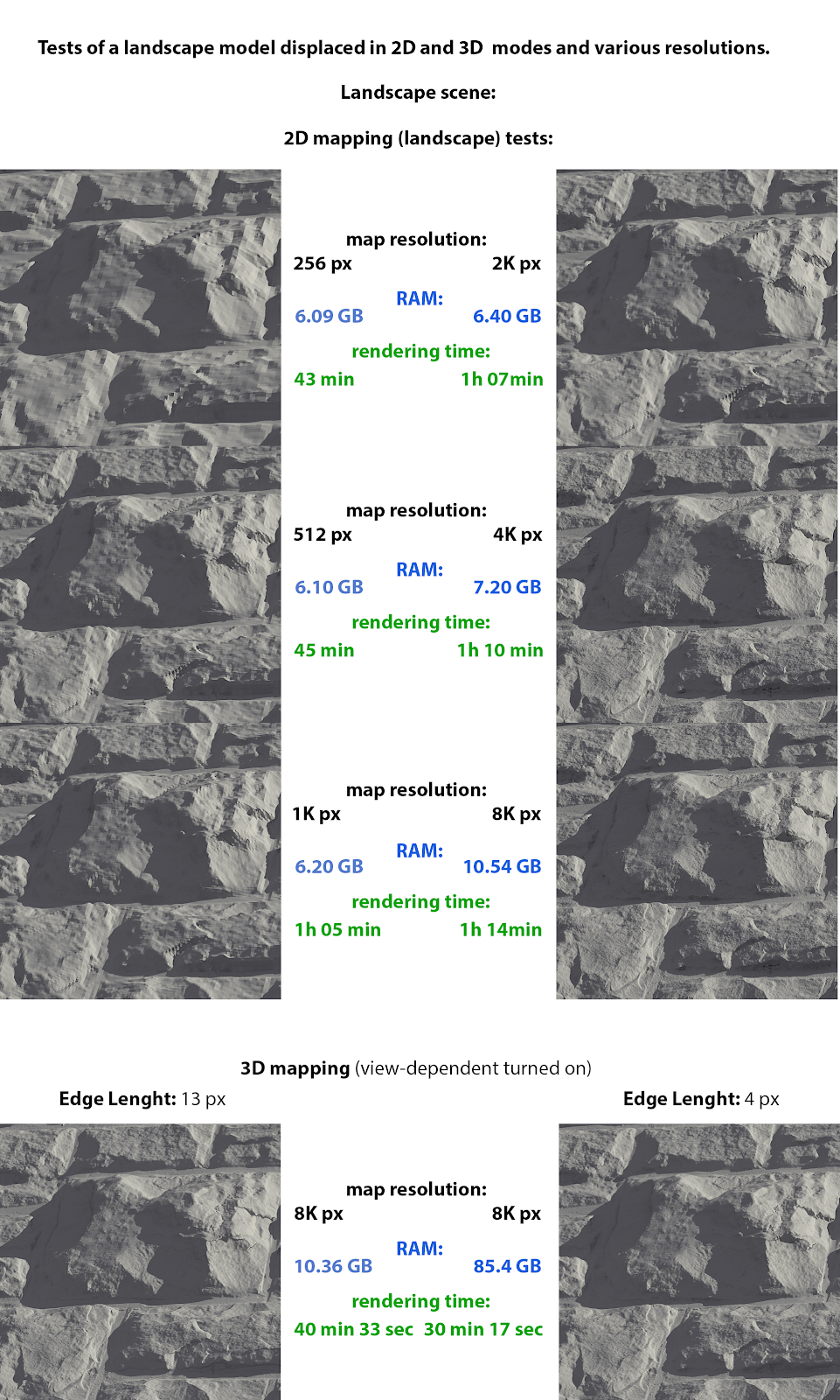
According to the tests, the scenes with 256 and 512 px displacement maps are not looking satisfactory. The texture pixels are visible in displacement. In the 1024 and 2048 renders the pixels are not so visible but there are visible low-quality artifacts on the steep edges of the rocks.
The 4096 and 8192 displacement textures rendered almost the same images, so we can discard the 8192 image which uses much more RAM, and leave the 4096 one.
The tests of the scene showed that RAM used by 2D displacement starts to rise quickly with the biggest maps. The 3D mapping with similar RAM usage gave a little more blurred displacement detail but it rendered much faster. 3D mapping displacement set to the highest possible level fitting on 128 GB RAM rendered an image not much better than set to 13 px, but with this zoom level and resolution, it’s restricted by the texture itself.
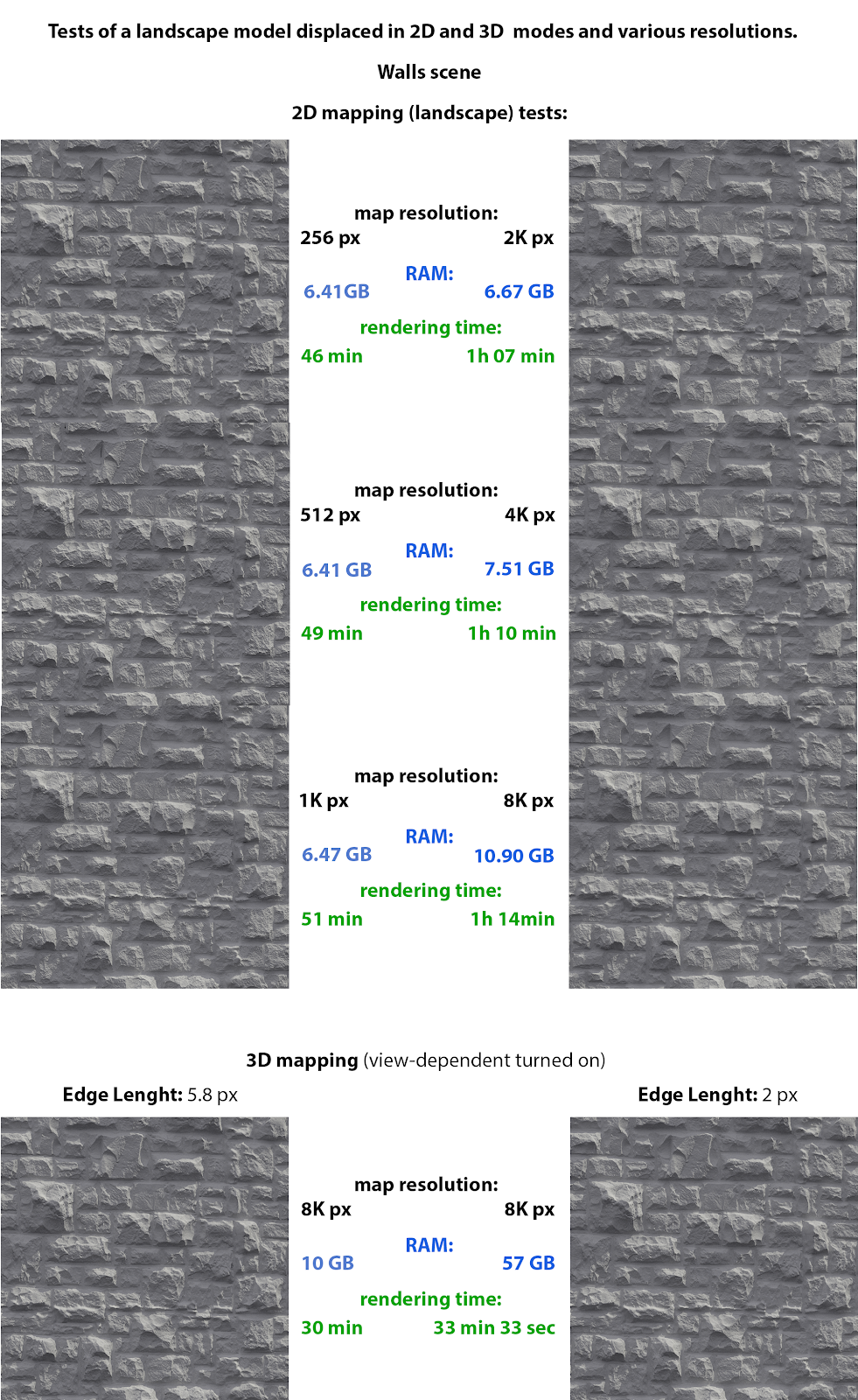
In the case of the second scene, renders from 256 to 2048 px maps are not looking satisfactory. They have visible displacement map pixels which vanish at 4096 resolution. 8192 map rendered almost the same but it reduced the number of random artifacts, at the cost of much bigger RAM usage.
A 3D mapped scene set to render with 10GB RAM used (we used 8K texture) gave an image with quality somewhere between 1024 and 2048 and 4096px of the scene in 2D mode. Also, the scene set to a maximum possible Edge Length of 2px and 57 RAM usage has less crisp detail than 2D displacement scene. However, it rendered much faster.
TIP: In 2D displacement mode it’s best to match the texture resolution in the displacement settings to the real resolution of the texture. If you need to run quick tests and shorten the time till you see the first pixels of the image, you can set the resolution in the modifier to a low value and set it back to the full value for normal rendering.
Let’s test a model with various densities of the mesh, but displaced with the VrayDisplacementMod setting set to the same values for every render.

Subdividing the mesh before applying VRayDisplacementMod saves a lot of RAM, sometimes at the expense of slightly longer rendering times. After reaching a certain threshold of mesh density, the use of RAM starts to grow again.
That’s because V-Ray displacement divides the geometry faces into sub triangles before applying the shift. It loads and subdivides one face after another, so if the model is built from a few big faces, V-Ray will need to work on very large parts of the model and calculate a very large mesh for that face. That can produce the need for more RAM.
On the other hand, when V-Ray starts the initial calculation of the mesh, it needs to keep as much of the displaced mesh in the memory as possible. This way it can calculate the adjacent edges to keep its continuity. If the displaced mesh gets too dense, it has to keep too many elements in the memory and take too much RAM.
Adding more subdivisions to the mesh before applying displacement can also help you to get better quality and get rid of the displacement artifacts. Here is an example:
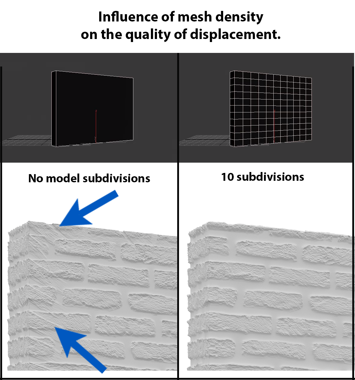
You can quickly subdivide the mesh using modifiers like Turbosmooth, however, it may give very small results if you won’t collapse the mesh to Editable Poly.
TIP: You may try to use Brute Force as a secondary bounce engine since it is more optimized in terms of memory usage. Light Cache has to load all the assets in order to proceed with calculating while BF and Irradiance Map can to it per bucket.
TIP: In some cases, it may be possible for you to combine either a bump or normal map with a displacement map on the same model. You can use displacement to bigger features and normal or bump for the finer detail.
Now, let’s try other methods of optimizing displacement rendering.
V-Ray renders the whole model with displacement applied, even the parts which are not visible in the shot. They can be visible in reflections or refractions through and affect rendering GI, so they are taken into calculations.
In the tests below we moved the models just outside of the camera view. In the first two tests models with displacement reflect on the surface of the ball.
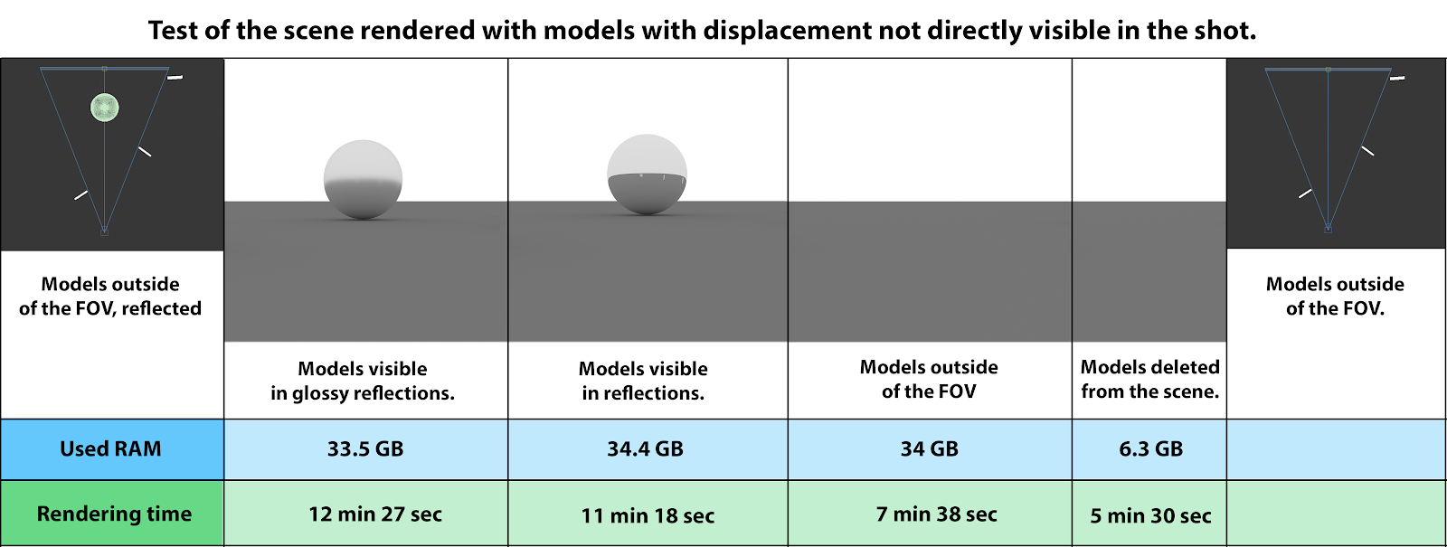
The amount of used resources drops down only when we delete the models with the displacement. If we need the displacement to be visible only in reflections, in many cases just the bump mapping is enough.
We can delete the parts not visible in the shot, for example by cutting and detaching the part of the model which is not visible in the frame.
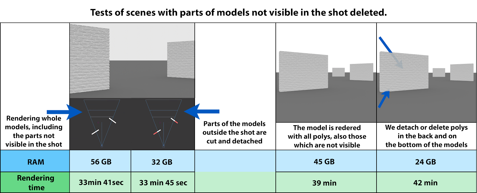
The polygons from behind the model can be deleted with no effect on the rendered image. The amount of saved RAM is substantial though.
Let’s check what happens when we render the scene with the render region turned on.

As you can see the amount of used RAM doesn’t change significantly. That’s because V-Ray is loading the whole model from the frame to memory, even if it’s not encompassed by the render region.
Sometimes using displacement is not needed at all for achieving a good result. In cases when the object is far away from the camera, the regular bump is enough.
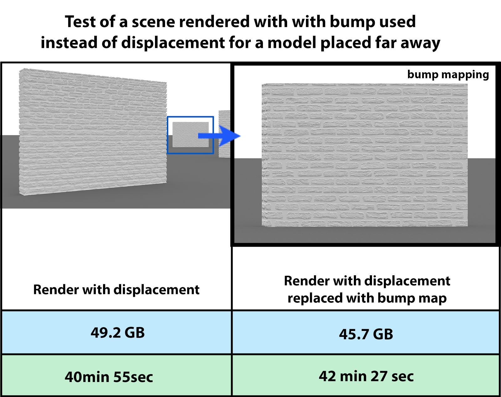
When can I use bump to cut on the used resources without a visible drop in the quality of my renders?
Using the Conserve memory option is a quick way of saving around 5-10% of the used RAM at the expense of slightly longer rendering times. Let’s have a look at the results of the tests. (We use the same scene as in the last tests.)

You can turn it on in Rendering > Render Setup > Settings > Conserve memory.
The settings mentioned below are by default turned on or off for the type of displacement you are using. It’s better to leave them like that, they are mostly used for helping your scene render when it completely gets out of hand, when V-Ray displacement gets into conflict with other plugins, and to bypass artifacts and bugs.
However, you may want to play around with them to see if they help to render your scene.
TIP: If you experience a peak of memory usage which is too high during calculating the GI phase, you can first render the GI to file with displacement turned off in the scene\object and then render your scene with GI loaded from the file with displacement turned back on. That trick may give good looking results in case of very small displaced features.
Static geometry – default enabled – displaced geometry is precompiled to an acceleration structure at the beginning and remains there until the end of the frame – it speeds up the rendering but increases memory usage
The dynamic memory is used for displacement surfaces only if you have turned off “static geometry” for it. The tiled textures and V-Ray proxies are stored in dynamic memory while regular geometry, non-tiled bitmaps and any other data required for rendering, stay in the static memory.
TIP: Displacement with static geometry turned on will render faster but at the cost of bigger RAM usage. In this case, the whole displacement is precalculated and stored in RAM. If you turn it off it will be stored in “dynamic memory” and loaded and unloaded according to needs during the rendering. In such a case you need to set your Dynamic Memory Limit to a value around 10 GB smaller than your computer’s RAM. It will allow V-Ray to store data in Dynamic Memory and leave some memory for the operating system and running applications.
To help it render as efficiently as possible set Dynamic Memory limit in Render setup > Settings > Dyn.mem.limit to a value of your computer’s RAM minus RAM needed for other applications and 3ds Max itself with a loaded scene (let’s say 5-10 GB less).
Tight bounds – default enabled (after V-Ray manual) – When enabled, V-Ray will try to compute the exact bounding volume of the displaced triangles from the original mesh.
This requires presampling of the displacement texture, but the rendering will be faster if the texture has large black or white areas. However, if the displacement texture is slow to evaluate and varies a lot between full black and white, it may be faster to turn this option off. When it is off, V-Ray will assume worst-case bounding volumes, and will not presample the texture.
You can use this option when the precalculating displacement takes too long so that V-Ray will sample the displacement only in cases it’s really needed.
TIP: The presampling phase for displacement is used to determine a more precise bounding box for the displaced geometry. You can skip it if you turn off the “Tight bounds” option in the displacement modifier. Especially for cases with more or less regular displacement maps, like grass, checkers, etc, turning this option off may speed up the initial part of the rendering process.
Cache normals – default disabled – When this option is enabled, V-Ray generates and saves information about the normal of each newly generated vertex. This requires additional memory but speeds up the shading calculations during rendering.
TIP: In the first part of the guide I mentioned that 3D displacement set to very low Edge Length leaves an effect similar to normal or bump mapping. You can turn off this effect by checking off the Cache normals box.
Relative to bounding box – default disabled – This setting binds the amount of displacement to the size of the bounding box of the model so it’s not really good for optimizing.
Poorly optimized displacement settings almost always affect the RAM usage of the scene. The rendering time can be affected by a bigger degree when the RAM usage reaches the level where the 3d application has to swap memory on HDD using it as virtual memory. In worst cases, the scene just freezes.
The first rule of optimizing displacement is the same as in the case of optimizing geometry. We need to give the computer the least data to compute as possible to obtain the effect we want. Since V-Ray displacement is taken into calculations also if it is not visible in the FOV of the camera, the easiest method is to delete all parts of the displacement models which are not visible in the shot.
2D displacement is often chosen because of its crisp results, but the RAM usage can go up very quickly with high-resolution maps. Also, 2D displacement with too low-quality options set looks less natural than low-quality 3D displacement, because of displacement map pixels visible on the displaced surface.
Adding some additional subdivisions to the displacement geometry also helps to cut on RAM and in effect, the rendering time. V-Ray will be able to work on smaller parts of the geometry at one “bite”. However, setting it to too dense mesh will fill up RAM again.
Conserve Memory is a very quick way to save around 5-10% of the memory at slightly longer rendering times.
Other options like Tight Bounds, Static Geometry and Cache Normals provide a choice between lower RAM usage and faster rendering times.
https://www.cggallery.com/tutorials/displacement/
https://docs.chaosgroup.com/display/VRAY3MAX/Displacement+Modifier+%7C+VRayDisplacementMod – V-Ray 3.6 documentation
https://docs.chaosgroup.com/display/VRAY4MAX/VRayDisplacementMod – V-ray 4 documentation
https://forums.chaosgroup.com/forum/ – Chaos Group forums
Own experience and tests
Textures used for illustrations and tests are taken from https://www.textures.com/ and https://texturehaven.com/
This guide has been created by Michał Moś and edited with the help of the team at GarageFarm.NET. We derived most of the knowledge used in this guide from an extensive experience running a render farm for almost a decade as well as from the Autodesk Knowledge Network and Chaos Group V-ray documentation. Textures used in the tests are from https://www.textures.com/ and https://3dbee.it/.

Michał Moś ( aka ‘Andrew’ ) is part of GarageFarm.NET team specializing in 3d rendering topics from animation and troubleshooting to technical writing. He has worked for numerous design and architectural companies as a CG artist, designer, and instructor. Weapon of choice – 3ds Max, C4D, V-Ray and Octane. He loves drawing, creative writing, and tabletop RPGs.
https://michalmos.carbonmade.com
https://blog.garagefarm.net/


